Documents
Calibration and Validation of SWOT Oceanographic Products Using the Permanent Facility for Altimetry Calibration in West Crete, Greece
S.P. Mertikas (Geodesy & Geomatics Engineering Lab, Technical University of Crete - Greece), C. Donlon (European Space Agency - the Netherlands), C. Mavrocordatos (European Space Agency - the Netherlands), P. Femenias (European Space Agency - Italy), I.N. Tziavos (Aristotle University of Thessaloniki - Greece), A. Tripolitsiotis (Space Geomatica - Greece), D. Galanakis (Space Geomatica - Greece)
1. Introduction & Objectives
Calibration and validation of the Surface Water and Ocean Topography (SWOT) mission has been recognized as a primary research priority for the SWOT Science Team for both hydrology and oceanography. The establishment of appropriate ground‐based but also aerial infrastructures in various environments and worldwide, will contribute towards the accomplishment of the SWOT scientific and technological objectives.
The technological advancements of the SWOT mission pose critical questions to the international satellite altimetry Cal/Val community:
- How can the 2‐D ground truth reference observations be established for sea‐surface calibration for the SWOT mission?
- Are there any alternative approaches for calibrating this new altimetry mission?
- Can we provide post‐launch calibration of the interferometric antennas baseline length and its orientation in space?
The main goal of this research is to answer these questions and carry out absolute calibration and validation (Cal/Val) of the SWOT products using the Permanent Facility for Altimetry Calibration (PFAC) in west Crete, Greece.
The PFAC infrastructure has been continuously operational as of 2004. Since then, estimation of absolute altimeter bias for the Jason‐1, Jason‐2, Jason‐3, SARAL/AltiKa, HY‐2A, and Sentinel‐3A altimetric missions has been continuously determined and disseminated.
Currently, PFAC establishes new altimetry standards using the concept of fiducial reference measurements. This will act to serve as the “yardstick” for evaluating the performance of all altimetry missions with documented procedures, protocols, and with results tied to international SI standards and parameters in an open and transparent way.
2. Approach
2.1 Two Dimensional Ground Truth Fiducial Reference Measurements
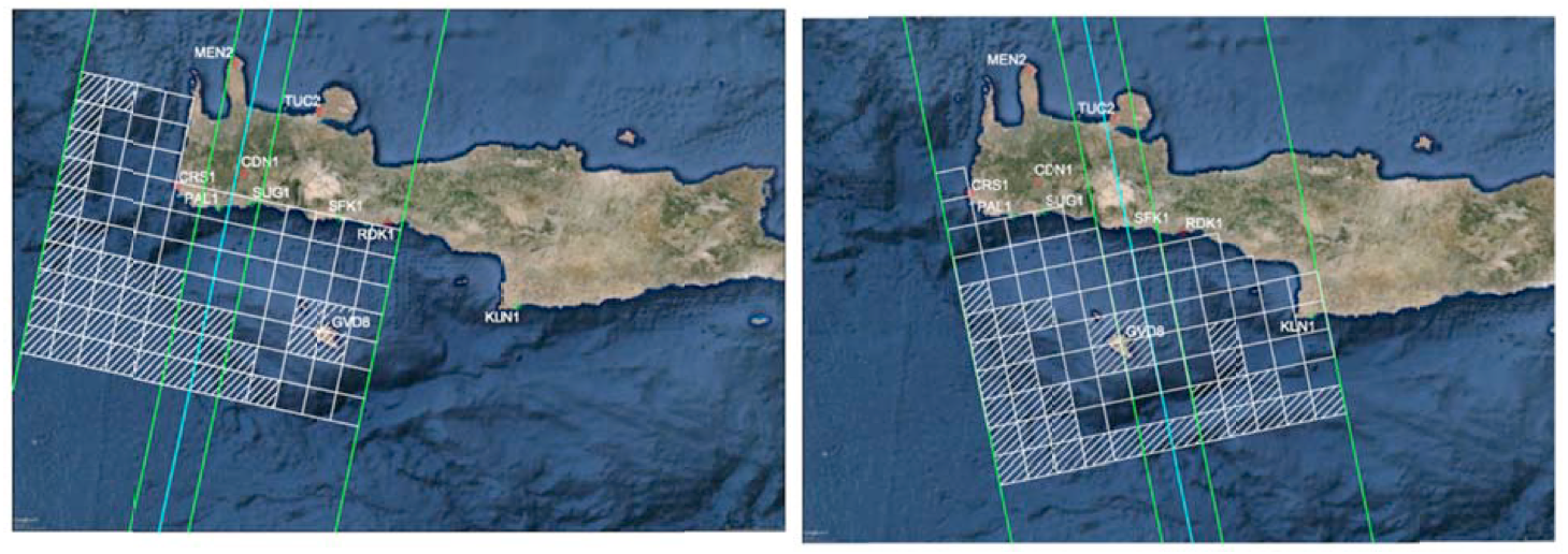
The main problem for employing the conventional and standardized sea‐surface calibration methodology for the calibration of the SWOT mission is its wide (~120 km) swath. This means that the permanent calibration sites primarily used for nadir altimeters are not that valuable for the SWOT calibration per se, as they provide a single point observation for the sea level. For nadir‐ looking altimeters this calibration point (or line) is satisfactory, because the satellite altimeter flies over the site. Nonetheless, this is not enough for wide swath altimeters. For the SWOT mission, in‐situ sea‐surface heights have to be obtained now over a large calibration surface area, extending up to 120 km.
The location of the existing PFAC sea‐surface Cal/Val sites (such as Gavdos, CRS1, RDK1) is characterized by small tides, rather simple ocean current circulation, and sea depths which exceed 3500 meters in some regions. Based on our long‐term experience and the specific characteristics of this PFAC location, it is accurate to estimate an effective calibrating region of 30 km for each Cal/Val site. Thus, three new sea‐surface Cal/Val sites are to be established in selected locations (i.e., SFK1, SUG1, and KLN1) to provide 2‐D in‐situ measurements for both the SWOT ascending Pass No. 58 and its descending Pass No. 349 (Figure 1).
An alternative approach is investigated to provide 2‐D ground‐truth measurements with the deployment of aerial or marine remotely operating vehicles while SWOT overflies the PFAC. These ROVs are to operate in swarm formation, be fully autonomous, exchange information amongst them and adjust their flight plan to fill unmonitored areas, etc.
2.2 Alternative Approaches for SWOT Calibration
Three alternative approaches are investigated under the framework of this project provided that availability of support is secured to perform appropriate software and hardware modifications in the PFAC infrastructure and instrumentation.
2.2.1 Relative Calibration
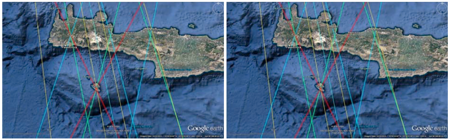
The conventional sea‐surface calibration methodology constitute an absolute indirect technique. This team investigates the relative calibration of SWOT mission products against baseline altimetry missions such as the Jason series (Figure 2).
2.2.2 Transponder Calibration
The CDN1 transponder Cal/Val site established on the mountains of Crete, Greece has been operating continuously since Sept 2015 for the calibration of Jason‐2, Jason‐3, Sentinel‐3A and CryoSat‐2 missions using a prototype microwave transponder (Figure 3).
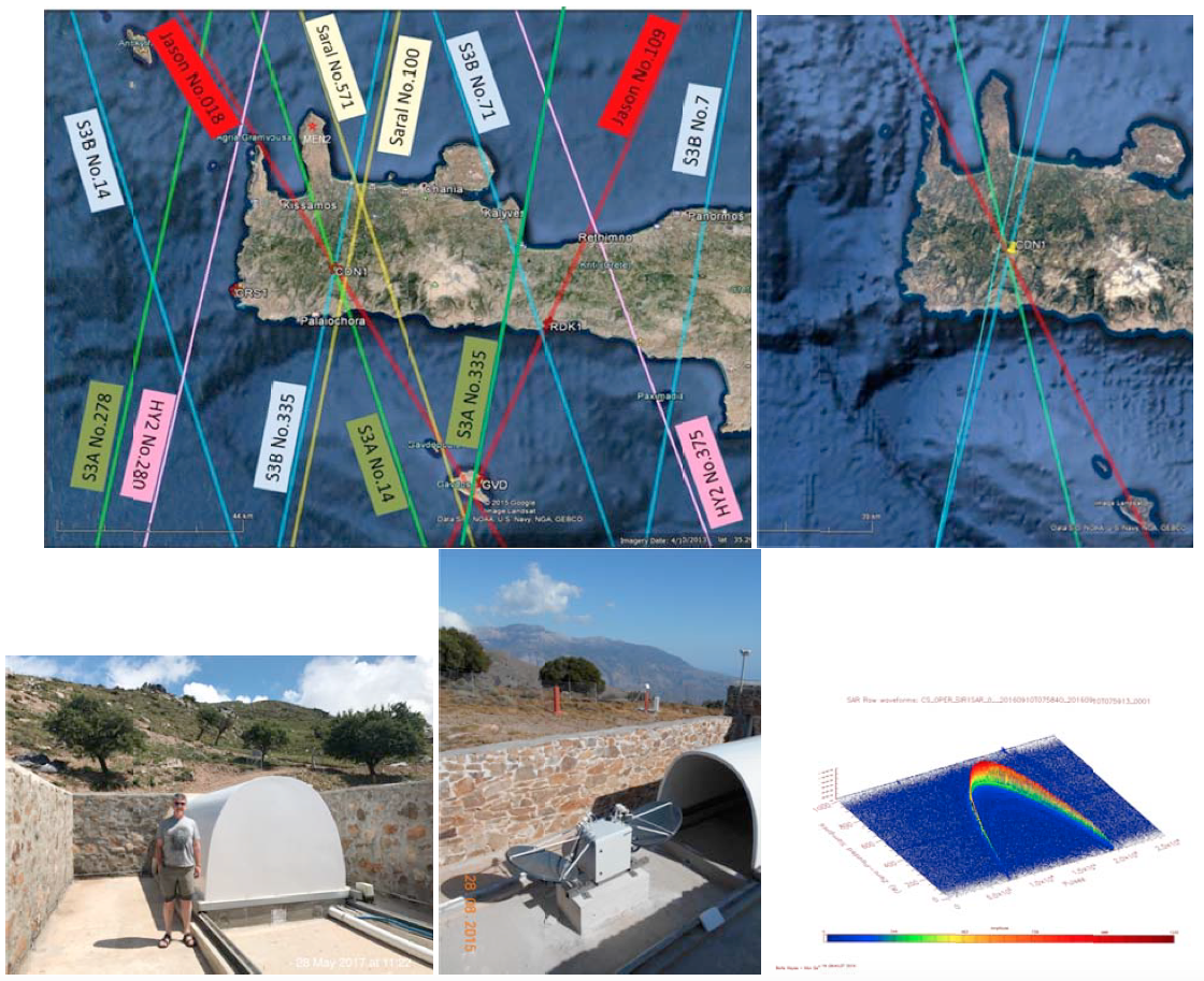
The SWOT mission will employ the KaRIN altimeter which differs primarily from reference altimetry missions in the operating frequency and in the two dimensional coverage for ocean topography. Nonetheless, the CDN1 transponder is planned to be modified to operate in the Ka‐band and thus be able to receive the SWOT signal as well. In addition, a network of additional ground equipment that will provide a network of true reference and fundamental values for the SWOT Cal/Val in the west Crete, Greece are under construction.
2.1.1 Sea‐surface & Transponder Calibration
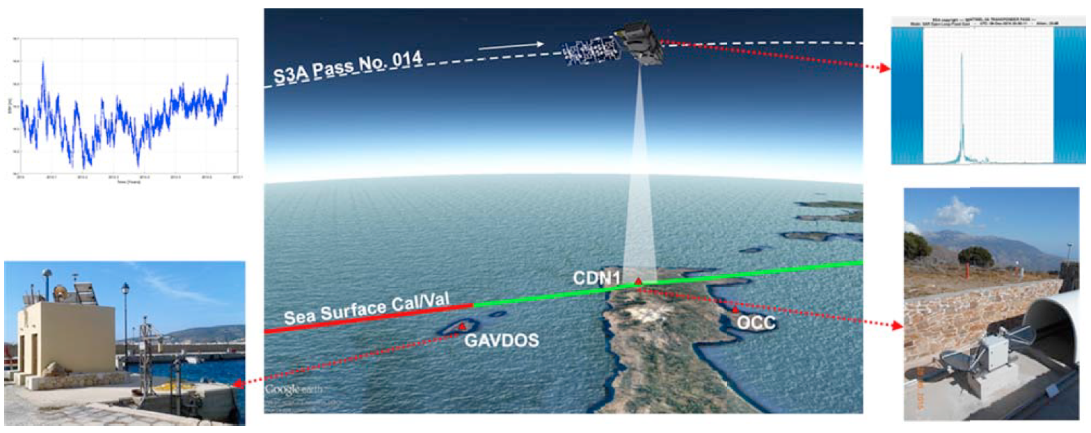
One of the unique characteristics of the PFAC facilities is that they provide sea‐surface and transponder calibrations at the same infrastructure, location and setting even for the same satellite pass (Figure 4). This capability will be carried out for the SWOT mission Pass No. 58.
2.2 Interferometric Antennas Post‐launch Calibration
The return radar signals, transmitted by the satellite altimeter, will be simultaneously received by two antennas in the SWOT, separated by 10m. The CDN1 transponder may serve as a point target and after some modifications it will be used to precisely measure the distance between the two SWOT antennas as well its baseline orientation in space.
3. Analysis & Anticipated Results
The approaches presented in earlier sections have been successfully employed for the calibration of Jason‐2, Jason‐3, CryoSat‐2, and Sentinel‐3A missions. Thus, the following results are planned for the SWOT:
- Determination of absolute altimeter biases and its drifts based on the Fiducia Reference Measurements concept in order to build up a climate change record for the future. Results will be built upon SI‐tracability standards but also based on three independent calibration methodologies (sea‐surface, cross‐overs, and location and setting; transponder) at the same infrastructure.
- Any directional errors in ascending and descending passes will be reported at the same reference calibration sites in PFAC.
- Cross‐calibration of various satellite altimeters is planned.
- Estimation of the SWOT interferometric baseline length and its orientation in space.
Acknowledgments

Part of this work has been produced with the financial assistance of the European Union. The views expressed herein can in no way be Union and/or European Space Agency.